A few weeks ago, I came home to an unfortunate surprise: my garage door was wide open to the world. While none of my precious junk seemed missing, I was embarrassed to have had my mess laid bare for the the neighborhood to see. As it turned out, the problem was a failed button connected to my door. I checked online and found that this unit was prone to failure. Worse than that, when these units fail, they open and close your garage door at random. I wanted a better solution in the form of a garage door controller.
I experimented a bit with the wiring and found something surprising. Turns out, to open the garage door, you simply need to short the two opener wires together. I decided to attempt to create my own, wireless enabled garage door controller based on an old Raspberry Pi B I had lying dormant. Here’s how I made it happen.
The Requirements
I wanted a garage door controller which had the following features:
- Could open and close the garage door (well, duh)
- Could detect the door state (open or closed)
- Had a timer that would close the door if opened for a configurable period of time
- Allowed the user to disable the timer easily, if needed
- Could send an email alert if it could not shut the door or if the door was open for an extensive period of time
The Hardware
I needed more than just my little computer to make this happen. My prototype eventually required the following bits and pieces.
- A Raspberry Pi (I recycled an old B I had lying around; but, any will do)
- 1 LED for the power indicator (RED)
- 3 LEDs (preferably a different color from the power LED, YELLOW in my case) for timer status indication
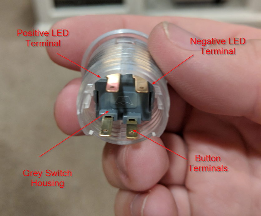
- 2 buttons, preferably with built in LEDs (I used these Adafruit Mini Arcade Buttons)
- A magnet switch with a “normally open” option, as typically used by alarms (I used this)
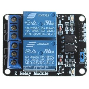
- A 5V relay module (I used this as it was in stock at my local electronics store; but, you don’t need two relays)
- 3 10k Ohm resistors to be used as “pull-up” resistors
- 4 330 Ohm resistors for the power and timer LEDs (note that the buttons I used contain their own LEDs and resistors)
- ~10 ft of bell wiring to wire the door open sensor switch
- A spring terminal block like this one to connect my magnet switch
Additionally, for prototyping, I used:
Finally, my design required a few prototyping printed circuit boards like these.
The Tools
I utilized a very simple soldering iron and some lead based solder (if I end up doing a lot more electronics work, I may switch to lead free).
For the enclosure, I made the design using FreeCAD and printed it using my Monoprice Maker Select V2.1 3D printer. The printed enclosure isn’t strictly necessary, and a wood enclosure would work just as well if that’s your jam. More on the enclosure later.
The Software
I built my own controller software using Ruby and the rpi_gpio gem listed here. I have placed the software on Github.
The software utilizes several threads to “listen” for button presses. Additionally, the software maintains a log of when the door was last opened. If the door has been open longer than the current timer setting, the software simulates a button press of the garage door button. If the door has been open for an excessive amount of time or the door failed to close, the software sends an alert email.
Wiring the Components to the Pi
To simplify my design, I broke my circuitry into two steps- wiring LEDs to indicate state and wiring switches / buttons to control state. Below, I’ll outline both sets of wiring.
Note that all wiring listed below is using the BCM numbering, not the board numbering.
Timer Status LEDs and Button LEDs
The standalone LEDs I purchased required 330 Ohm resistors. For any LEDs you purchase, check the requirements of the LED and modify the resistors accordingly.
To start, I wired my RED power LED with a resistor to the 5V rail of the Raspberry Pi. This LED serves as a sanity-check that your Pi getting and outputting voltage. The YELLOW status LEDs are to inform the user which timer setting is currently active (5 minutes if the first is lit, 10 if the second is lit and 15 if the last is lit). I wired these to GPIO pins 4, 17 and 27, respectively, along with their resistors.
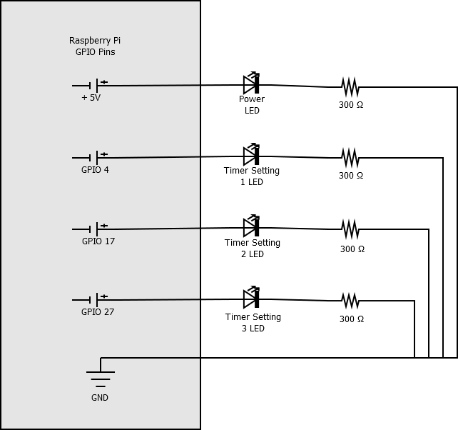
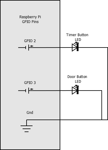
For the button LEDs, the garage door opening button (blue, in my build) should stay on whenever the system is running. The timer button (white) should stay on when the door is shut and the timer is “armed,” blink when the door is opened and turn off when the timer is disabled.
I wired the timer LED to GPIO pin 2 and the door LED to GPIO pin 3.
Wiring the Door Open Sensor Switch and Buttons
To connect my two buttons and door open sensor switch, I used 10k Ohm resistors to “pull-up” the voltage to the pins. The way this works is that the buttons open a more direct path to ground than the GPIO pin. So, if I detect that my GPIO pin voltage goes “low,” I know the button is being pressed. Additionally, I could configure the door open sensor switch in one of two ways: normally open or normally closed. This means that, if the door is closed and the magnet is near the sensor, the circuit will either be open or closed, respectively. I chose normally open so that if I ever have a short in my system, the controller won’t mistake the door for “open” and try to open it after the timer resets.
I wired the door sensor switch to GPIO 7, the timer button to GPIO 8 and the door control button to GPIO 25.

Wiring the Relay Module
Finally, the heart of the garage door controller- the relay module. When the relay module’s voltage is set to high, a magnetic switch closes a circuit and shorts our garage door wires together. The application shorts these wires for about 1 second, as that circuit isn’t meant to be closed for a long period of time.
I wired the GND pin of the relay to a ground pin, the VCC pin to a 5V pin and the IN1 pin to GPIO 24 on the Pi. On the first relay module, I put one of the wires coming from my garage door into the center terminal and the other into the terminal that is indicated as “disconnected” by the diagram. This configures the relay as “normally open,” meaning the wires are NOT shorted together unless a signal is sent from the Pi (GPIO 24 is set to high).
Testing the Setup
I put that all together into my setup, creating quite a Frankenstein mess of wiring.
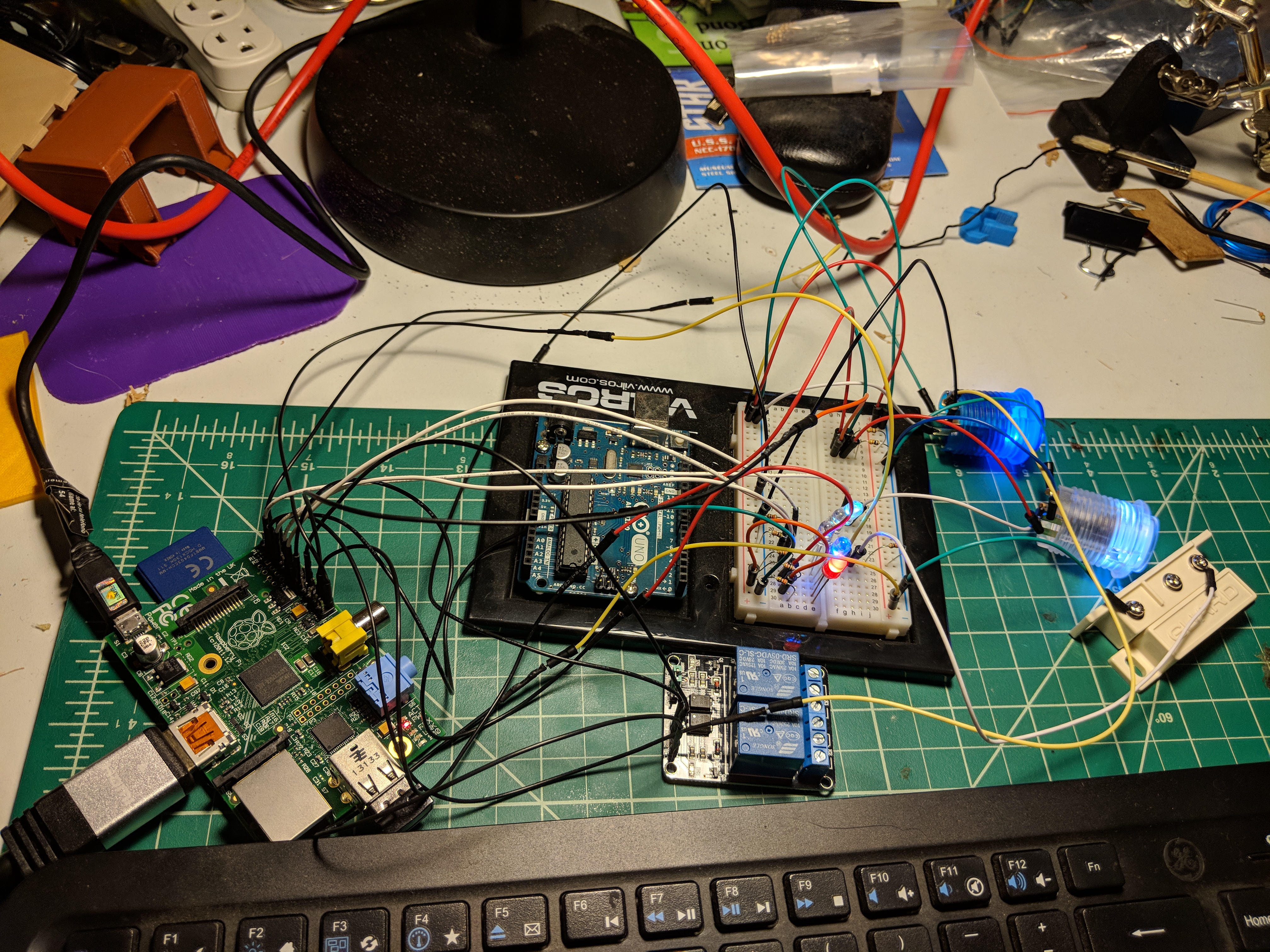
From here, I built the software and ran daemon_start.rb in my project. Pressing the blue (door) button produced a satisfying CLICK as the relay closed and then opened again. Pressing the white (timer) button cycled the yellow LEDs through each setting. Moving the motion sensor switch magnet away from the sensor caused the white (timer) button to blink, indicating an open door. Finally, after the timeout, I heard the system CLICK again as the timer engaged the relay. Fantastic.
But how do I make this rat’s nest of wires into a usable garage door controller?
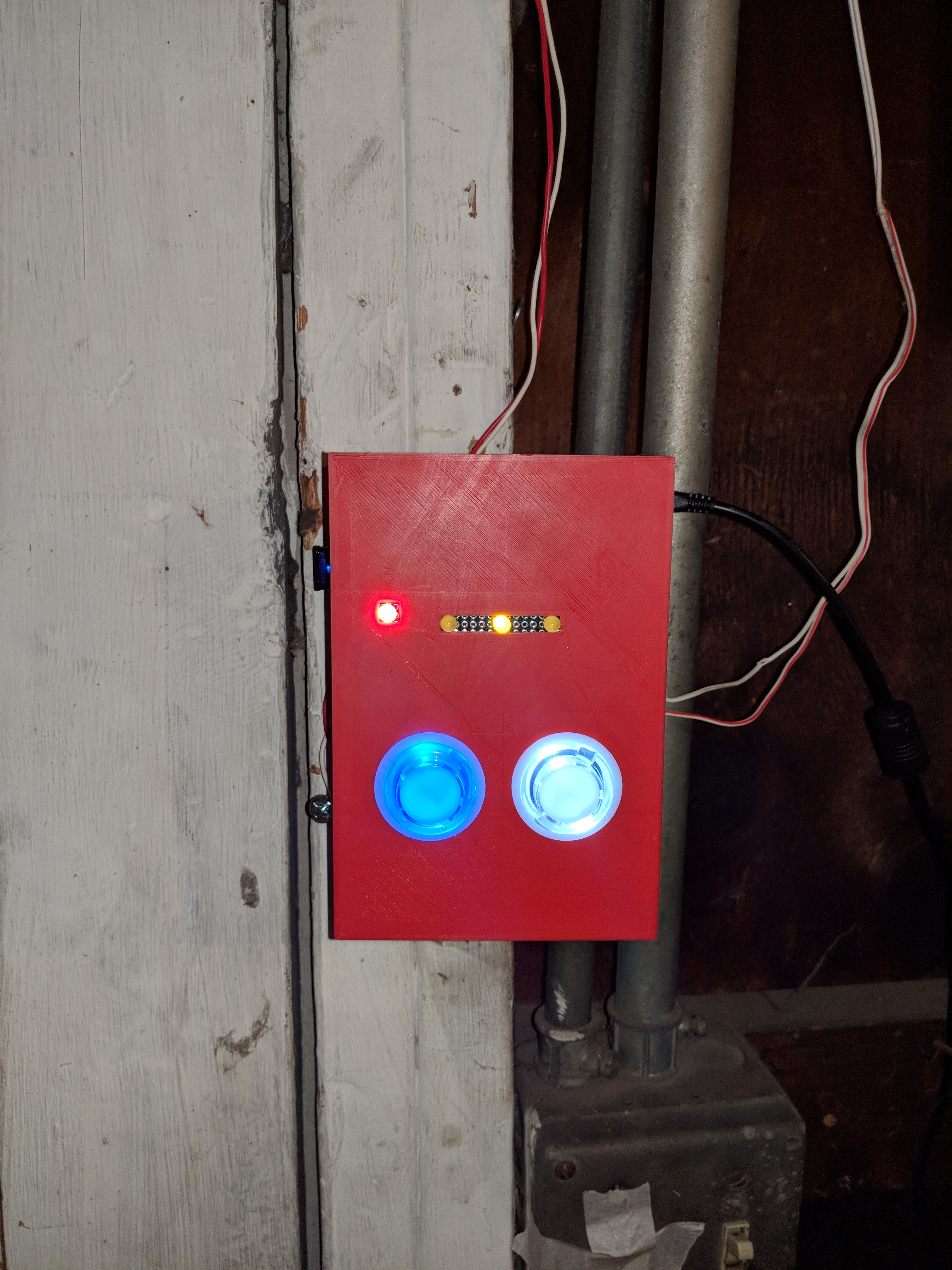
A More Permanent Build
I won’t go much into soldering or other techniques here. However, I’ll provide a brief overview of how I designed a more permanent version of this garage door controller.
First, I split the electronics into two daughter boards. One of the boards controls the power and timer LEDs. The other controls the buttons, door open switch and button LEDs.
I used 2cm by 8cm blank circuit boards and small gauge wire to make the daughter boards. These are the boards I used. On the switch and button control board, I installed a spring terminal to easily connect the bell wire leading to the door open sensor switch. I also purchased some small push-on terminals for easy connections to the buttons. Finally, I soldered headers to each of the boards and used female-to-female jumpers to connect the boards to the pins on the Raspberry Pi.
To hold it all together, I designed a case using FreeCAD and printed it using a 3D printer. If you are interested in 3D printing my design, you can find it on Thingiverse here.

The Raspberry Pi, relay and switch daughter board fit into the sections of the bottom portion of the enclosure.

My design leaves a bit to be desired. I used a bit of shipping tape to anchor the pieces together. Still, the overall final look is nice and functional.
And finally, a video of the device in action!